[BBS-¯å§ûóú]
Bando Radio Technic-5
by Kihwal Lee, HL1SUL
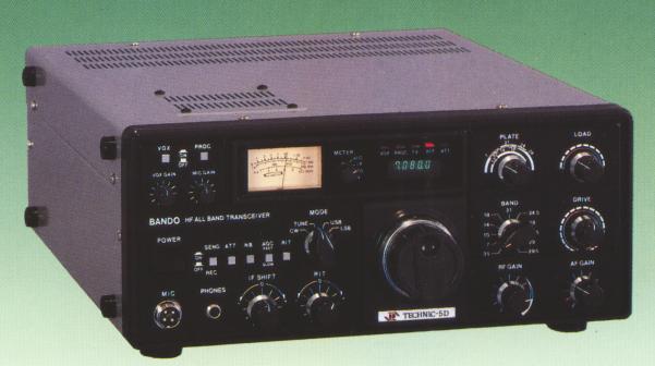
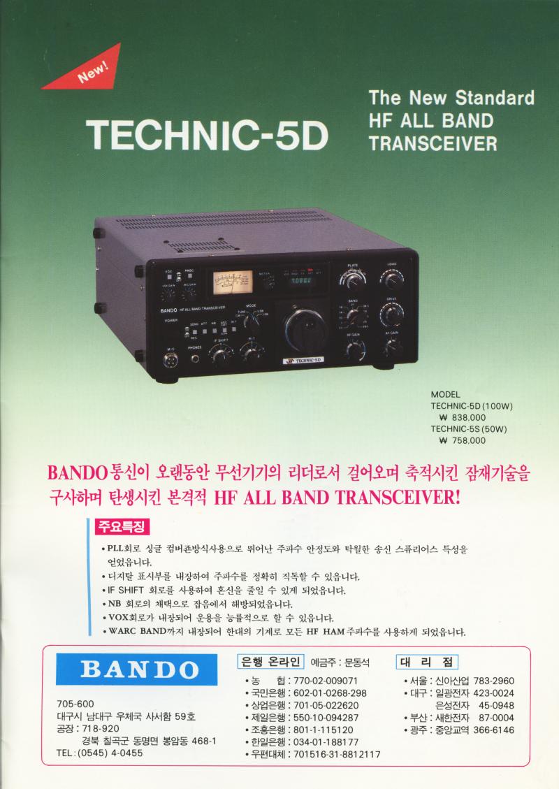
Technic-5D by Bando Radio
Background
Bando Radio is a Korean ham radio equipment manufacturer who existed from the early 80s to the mid 90s, for about 15 years. Bando was very successful thanks to the solid design and performance of their produtcts. The competitors produced the products with better appearances or lower price tags, but in the end Bando's performance and stability earned customer's trust.
Technic-5 is their only HF all band transceiver. Released in 1987, Technic-5 went though a design change in 1993. It was also sold in the VK area in the early 90s. The original designer was the founder and the owner of Bando, HL5BAP. The ownership was changed in September 1992 and the company was also relocated from Kyungbook area to Seoul.
There are two types of Technic-5: Technic-5D has two 6146B, capable of generating 100W output. Technic-5S has one 6146B for 50W output, suitable for A3 license holders in Korea. There was a major revision in its VFO design in 1993. The original VFO is an analog type but the revised version is more stable PLL-based. I have never had any issue on the VFO stability with the old version though. I suspect the real reason is the shortage of the key part used in the old VFO design.
Specification
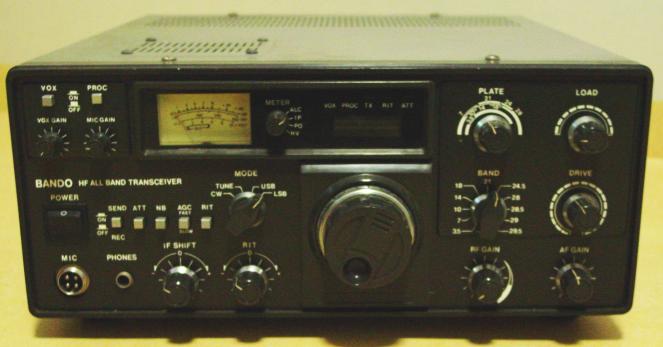
The front panel
Technic-5 is a typical analog HF transceiver with tube finals: two 6146s in the finals, a 12BY7A as a driver, an analog VFO, and a digital frequency readout.
It is equipped with VOX, speech processor, noise blanker, IF shift, and RIT. The meter can display ALC level, plate current, power out, and high voltage by turning the switch next to it.
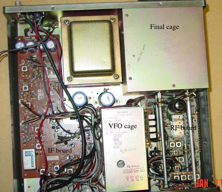
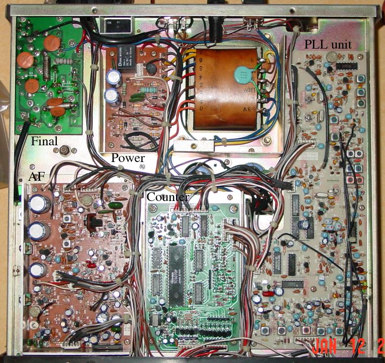
Internal Details
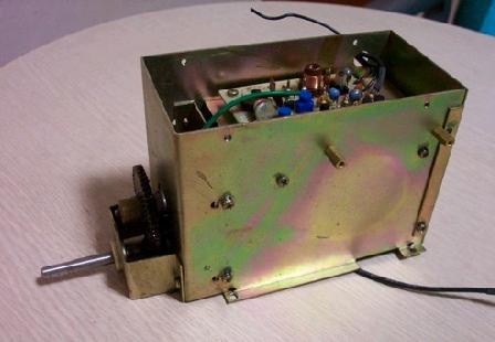 The VFO assembly. (Photo courtesy of DS2ISM) |
The original
Technic-5 utilizes Collins PTO with the cover removed! The designer of
the transceiver, HL5BAP must have had an access to a lot of supplus PTOs
and thought he would sell a several hundred transceivers at best. I guess
the sales of Technic-5 exceeded his expectation.
Upon the change of the ownership in late 1992, Bando Radio started working on the new VFO design. They also offered the upgrade option for the owners of the old version. The analog VFO had the variable frequency range of 500KHz. The PLL VFO is locked according to the Korean band plan. (e.g. 40m: 7000-7100 KHz) |
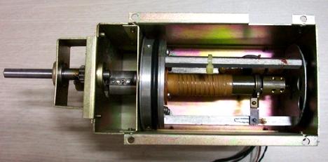
[Left] The VFO board on the top side of the cage. [Right] Collins PTO Inside (R)
(Photo courtesy of DS2ISM)
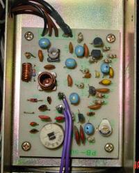
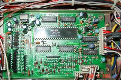
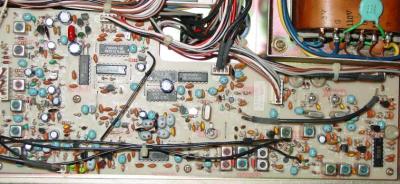 The PLL board | In the advertisement in 1987, Technic-5 is described as "PLL-based". It had been only half-true until the VFO revision. They did use PLL to replace the x-tal-based band switch OSC. The PLL board is composed of four parts: 1) x-tal carrier OSC, 2) PLL-based local OSC for band selection, 3) mixer for premixing VFO and the band selection OSC signals. |
|
|
|
|
|
Since VFO and band selection OSC are premixed, the receiver part of the transceiver is single conversion superheterodyne. There is only one crystal filter soldered on the IF board. The bandwidth is 2 KHz which is for SSB operation. There is no CW filter option.
|
|
|
|
|
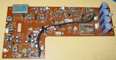
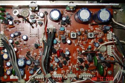
Technic-5 is very similar to Kenwood TS-530 down to the PCB and circuit level. Although the RF board is different in the parts layout, it is the copy of TS-530's RF circuit. It was divided into three sub-boards due to the space limit. The other units look very similar to the counterparts in TS-530. There are differences though. Most of all, Techinc-5 does not have notch filter. The IF frequencies are different (8.8MHz Vs 9MHz) and so are the VCO frequencies. The speech processors are also different. Technic-5's processor is in the IF stage after the x-tal filter, while TS-530's processor is in AF stage. Technic-5 has only enough space for one filter. Electronically, Technic-5 is 99% identical to TS-530.
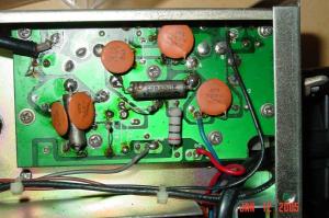 |
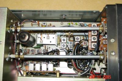
The final board with two 6146Bs. This is not the original construction. I have added one more 6146B and other parts to 50W model. |
Top view. The BNC connector in the top-left is not original. I added it to enable transceive operation with an external receiver
Bottom view
Modifications and Alignment
Most of TS-530/830 mods are also applicable to Technic-5:
1.TS-530S IF unit Q2, Q7 protection: In Technic-5, they are Q4 and Q10. You can achieve the same effect by installing the surge suppressor between the FG tip and the nearby TPG tip on the foil side of the AF unit. The both posts are marked on the PCB.
2.Power supply drift and stability improvement
This is for early TS-530's. Technic-5 is based on the later TS-530. So no change is necessary.
3.Enabling WARC bands: Technic-5 is fully operational on all WARC bands. No change is necessary.
4.TS-530/830's frequency drift and jumping symptoms also occasionally appears in Technic-5. The same remedies may be used. I had issues with the grounding of the AF unit.
5. The QRO mod is not recommended. The mod changes 6146's screen voltage from 210V to 300V. There are several reasons why it is not a good idea: a) 6146's lifespan will shorten, 2) the extra power does not make too much difference at the receiving end, 3) the transformer is not designed to handle that much load, 4) it is far too much of overspec if 6146W's are used, and 5) the transmission quality will suffer.
The following are my ideas:
1. Adding the SG switch: TS-530/830 has the SG switch in the back. In normal transmission, screen voltage of 210V is supplied to 6146s. In tune mode, the voltage is dropped. If SG switch is off, it is further dropped (negative?). It is used in neutralizing the tubes or transverter operations. The low voltage can be obtained by adding a 100Kohm resister to (-c) in Technic-5's power supply unit, just like TS-530.
2. Adding ALC input terminal: By feeding a negative voltage (e.g. -9V to 0V), the transceiver's output can be adjusted nicely. Put a 9V battery in reverse through a 1Kohm pot. It can also be place inside of Technic-5.
3. A mod for connecting to a linear amp.
4. A mod for operating with an external receiver.
Alignment:
 |
No alignment procedure is given in the instruction manual of Technic-5. Fortunately,
TS-530's operating and service manual provides all the necessary information. We
just need to map the part identifier between the two transceivers. Except the
RF unit, You can find the matching pots and trimmer caps by comparing the PCBs.
Complete mapping will be provided in the future.
Neutralizing the final tubes can be accomplished roughly the same way TS-530 manual shows. It is necessary to drop the SG voltage by temporarily modifying the circuit or adding the SG switch like TS-530's. After that, TC1 near the final unit is adjusted for the minimum output. If the frequency reading is a little off, calibration of the reference frequency in the PLL unit is in need. I think using a 10MHz standard time station is the easiest method. The reference on the PLL unit is 10MHz and it will be heard when you tune Technic-5 at 10MHz without an antenna. Connect an antenna and see if it zero-beats with the standard time broadcasting. If it doesn't, carefully adjust the trimmer cap next to the 10MHz x-tal on the board. Refer to TS-530 Service Manual for details. |
Links